Hi Fridolin,
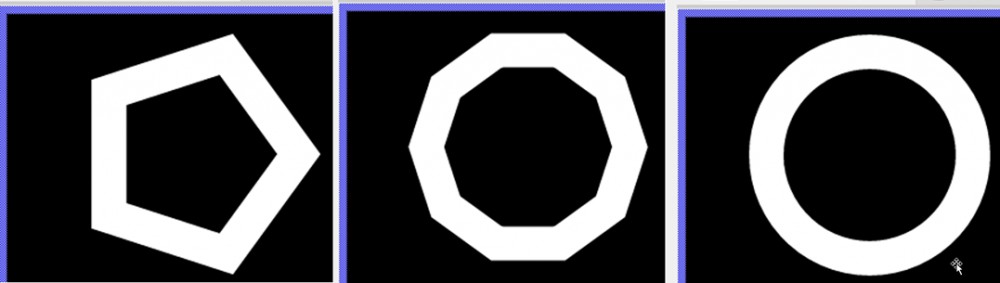
this is a quite interesting question, but it also needs some explanation. Embedded Wizard uses so called vector graphics for its internal modellation of a Stroked Path element. Technically a circle is nothing else then a lot straight lines, which are connected to each other. As more of them will be connected to each other, as more detailed the resulting circle will be. Please take here into account, that the number of line elements also affect the CPU and RAM usage which will be needed for the calculation of the circle. Following pictures illustrate a circle with the same diameter, but with 5, 10 and 60 line segments. Of course, the last one needs the most computing power, but also looks most smooth.
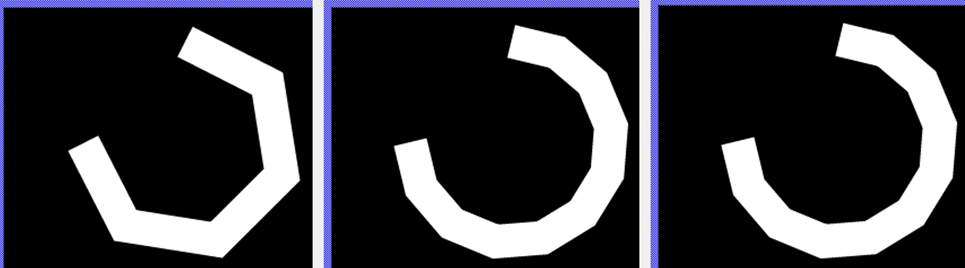
So, every Arc Path object will be stored as a certain number of straight lines with their start and end points as X-Y coordinates. The Stroked Path view object uses these coordinates to draw each single line and as result you can see the whole circle. Here each circle element is a short rectangle with rectangular ends which will be drawn along the circle path:
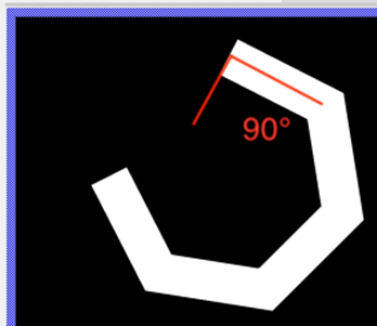
Thus, the effect that you have figured out is a correct behaviour. The next picture really good shows why the circle ends aren't rectangular to the centre of the circle.
To draw a circle as you wish, please do following two steps:
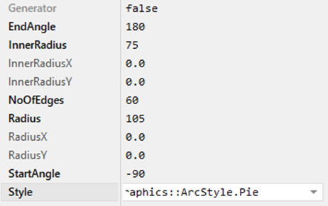
Step 1) Configure an Arc Path object with an InnerRadius and Radius in order to your needed line width. For example, for a circle with 30 pixel line width and 90 pixel as diameter, you have to set Radius to 90 + 30/2 = 105 and InnerRadius 90 - 30/2 = 75. Then please configure the setting Style to Graphics::ArcSytle.Pie.
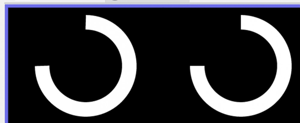
Step 2) Use and Filled Path view instead of Stroked Path view and setup the in step 1 configured ‘Arc Path’ object as Path parameter. The Filled Path object now draws a circle with end caps regarding to your needs. In following picture you can see the difference between Stroked Path (left) and Filled Path (right).
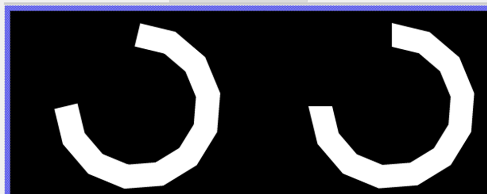
With this kind of modelling the number of circle elements can be decreased and this decreases the power needed for its drawing as well. Thus, even with a very small number of line segment, the end caps are rectangular to the centre of the circle. For example, here you can see a circle element with a really low number of elements.
Hopefully this helps to design your circle status bar properly.
Best regards,
Tim