428 views
in Platform Packages by

Hi EW friends,

 I have been recently debugging a weird issue on 9.30 opengl package. For example, a solid line lay behind a vertical list, when we slide the vertical list, the repaint order would be:

1、 fill all the dirty rect area.

2、 redraw part of the line which is intersected with the region

3、redraw the vertical list

However, we found there is an extra pixel rendered out side the actual dirty region of the line. shown as below:

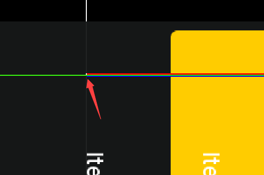
I have checked the dirty region, enabled the macro "EW_PRINT_GFX_TASK_DETAILS" to see whether the line is drawn with correct parameter, and the answer is yes according to the printed details.  However, when we deploy the same scene  with a surface rotation of 0 degree, it has no such issue anymore. Is it weird? 

Do you have any idea to go on with the debugging , or would you like to reproduce the issue? It has a 100% reproducibility.

BR

Arnold

1 Answer

0 votes
by
Hello Arnold,

the problem occurs only when rotation 90 degree is applied, right? Do you have eventually some scaling active? In other words: are the LCD resolution and the ScreenSize specified in Embedded Wizard different?

Best regards

Paul Banach
by
Hi Paul,

The ScreenSize is 1920x1200 (which is the same as it is set in ew studio), and the screen is a vertical screen, so we define the surface rotation macro to 90.

The problem did only occurs when rotation 90 degree is applied. Besides when we enable full screen update, the issue has disappeared. But for the performance concern, we can not afford to deploy full screen update.

BR

Arnold
by
Hello Arnold,

can you reduce the application case to a very simple example and provide it to us? We would try to reproduce the behaviour.

Best regards

Paul Banach
by

Hi Paul,

Here is the attachment (I adjust it to1920x1080 R90 for your convenience):

ew project

And I would like to share some extra information. We have make some modifications to integrate ew framework to our target board. To be more specific, we have redirected the rendering dst to off-screen fbos(as color attachment), so that we can handle more flexibly with the gui rendered output. There is a simple change of model matrix  as below:

It mainly flips the y coordinate to  cause the render output to texture is upside down.

Recently, I have dumped the frame before rendering the line and after rendering the line, the code snippet is shown as below:


And the result before draw this line and  after draw this line is :

Obviously, there is a pixel outside the due region. Could you help to figure out the possible reason?


BR

Arnold

by
Hello Arnold,

I have understood that you have modified the original Embedded Wizard implementation. I would at first restore the original version and verify whether the update issue still occurs. Especially the modifications in the model matrix can become very problematic. This may produce wrong coordinates and consequently lead to incomplete update areas. At first glance at your modifications, it is difficult for me to deduce whether and what an effect it would have on the functionality.

Best regards

Paul Banach
by

Hi Paul,

I'm here again about the issue, for we have an important discovery that the bug has relation with :

What‘s the purpose of the +/- 0.5f ? 

BR

Arnold


by

Hello Arnold,

when stroking a straight lines segment, the segment has to be drawn between the center of the starting and the center of the end pixel. Adding +0.5 to the X and Y coordinates moves the position to the center of the corresponding pixel. 

Referring to my preceding answer, could you test the behaviour with the original matrix calculation?

Best regards

Paul Banach

Embedded Wizard Website | Privacy Policy | Imprint

...