1.4k views
in GUI Development by
Hello. I'm trying to make something like "Climatic Cabinet" demo using Graph. And i can't figure out how to add more then 1 line. Thanks.

1 Answer

+1 vote
by
 
Best answer

Hello,

if you are talking about something like the "Climatic Cabinet" demo, then it might be better to work with the class Charts::LineChart instead of the class Charts::Graph.

A good starting point for working with the class Charts::LineChart is the example "ChartsDemo". If you prefer working with the class Charts::Graph, then have a look into the example "WaveformGenerator".

If your question "how to add more then 1 line" means, how to show several graphs within one diagramm, then you can place several Graph objects over each other - everyone is displaying one curve. In this case, the background color and the grid lines of all overlapping charts should be set to transparent.

I hope this answers your question.

The following example (taken from the "Vehicle Data Logger" demo application) shows this idea:


by
Thanks, that helped. Two more questions. I tried Charts::LineChart class but it looks like it doesn't support vertical grid lines, does it? And is there any way to name those grid lines, like it's made in "Climatic Cabinet" demo. I mean "20, 40, 60, °C, etc."?
by
You can place additional views like Views::Line or Views::Text into your chart in order to add additonal lines and description text items.

This gives you the possibility to place the text where you want, to choose the font that you want, or to add additonal icons...
by
Hello

Where can i find a example on LineChart ??
I can't find that ChartsDemo that you refer to

best regards
Håkan
by

Hello,

the Vehicle Data Logger will be part of the provided examples in one of the next versions. At the moment it is not completely cleaned and documented. Nevertheless, you can download the current version and adapt it according your needs.

Best regards,

Manfred

by

Hi,

For my application case I need a graph component like you have designed for vehicle data logger using charts:: graph but with more features.

This the graph view I want to create. At the runtime I need to plot the values send from the device side. maximum of 500 values we can have. X axis also need to be moved to display the current time interval. Sliding option to view the old and new values also need to be adapted. I will be thankful if you could please assist me to implement this graph view with those additional features? 

Regards,

Sazna.

by

Hi Sazna,

please note, that the vehicle data logger example is more than 8 years old and it was created with an Embedded Wizard version that did not support vector graphics. It will not be a helpful starting point.

Of course, you can implement your own graph class that fulfills all of the mentioned requirements. According to the feature set that you mentioned, it might be better to use a Graph template or to create your own graph component based on vector graphics.

You will find several different examples (Climate Cabinet, Waveform Generator, Pulse Oximeter, Oscilloscope, ...) delivered with Embedded Wizard Studio - each with different types of graphs. Let me recommend to have a look on these examples and then create your own implementation according to your needs.

We cannot provide an implementation that already matches all your application use-case - if you have a dedicated question, please let us know.

Best regards,

Manfred.

by
Hi Manfred,

By using vector graphics how can we display each points as dot bitmap and connecting each points by a line?

Regards,

Sazna.
by

Hi Sazna,

the dots can be drawn as Views::Image on top of the graph. As an example, please have a look to the LineChart template. There you will find the lines drawn by vector graphics and the dots drawn as images.

Best regards,
Manfred.

by
Hi Manfred,

Then is it possible to adapt scaling into the line charts?

Regards,

Sazna.
by

Hi Sazna,

within the example PulseOximeter you will find a graph that can be scaled and moved by the user. The template LineChart shows how to implement dots over a graph.

Unfortunately, there are so many different types of graphs and data logger possible, that we cannot provide an example for every custom specific use case. The mentioned examples in one of my post above, gives you a good introduction into this topic, so that you can put the things together that are needed in your case.

Alternatively, my colleagues from GUI Services are implementing graphs according to customers specifications. Maybe that is an option to consider.

Best regards,
Manfred.

by

Hi Team,

I went through the examples and found I can go with PulseOximeter example to achieve our custom design.  Below is the created graph component.

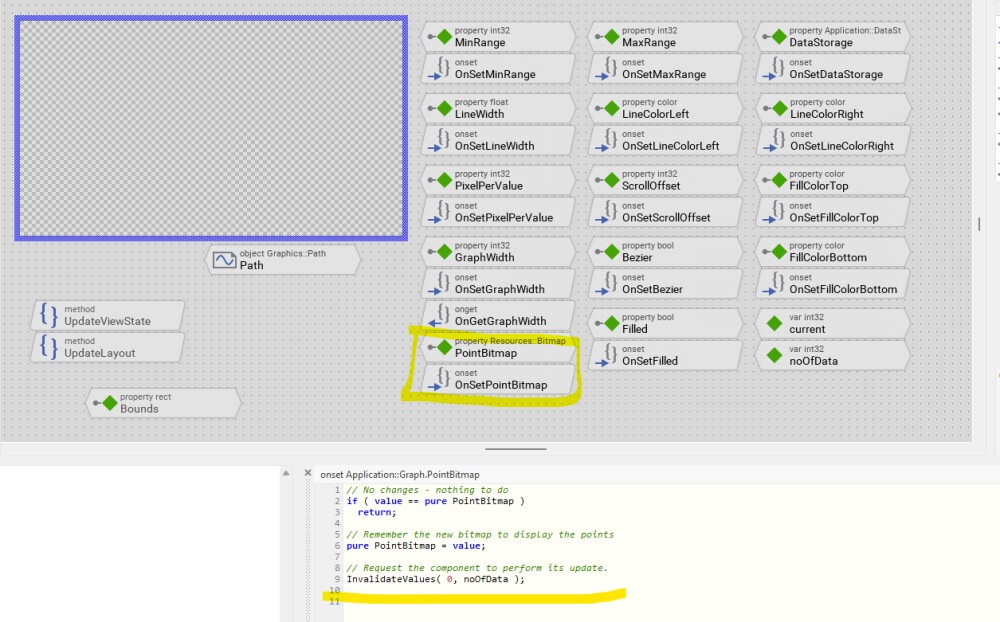
Here I have added a property point bitmap to show the value as dot. But I have no idea how I can adapt this to draw the graph . Graph is drawn through this below code.

// Always invoke the inherited method.
super( aState );

/* check if there are any data to draw */
if (( noOfData < 2 ) || ( ScrollOffset < -Bounds.w ) || ( DataStorage == null ))
  return;

var int32 inx;
var int32 x;
var bool firstRun = true;
var int32 noOfEdges = PixelPerValue / 4 + 1;

/* search for index and horizontal position of the first coordinate that is left of the views origin */
inx = ( ScrollOffset + Bounds.w ) / PixelPerValue + 1; 
x = ( ScrollOffset + Bounds.w ) % PixelPerValue - PixelPerValue; 

/* clear the path */
Path.InitSubPath( 0, noOfEdges * inx + 4 );

  var float data;
  var float slope;
  var float lastData = 0.0;
  var float lastSlope = 0.0;
   var int32 dx = PixelPerValue / 2;

  var float ratio = 0.25;
  

/* iterate through all visible data entries of the data storage */
while (( x < Bounds.w + PixelPerValue ) && ( inx >= 0 ))
{
  if ( inx < noOfData )
  {
    data = DataStorage.GetData( current - inx );
    slope = DataStorage.GetSlope( current - inx );

    data = (float)StrokePath.Bounds.h * ( data - (float)MinRange ) / (float)( MaxRange - MinRange );

    if ( firstRun == true )
    {
      Path.Begin( 0, x - (int32)LineWidth, /*StrokePath.Bounds.h / 2 */ 0 );
      Path.AddLine( 0, x, data );
      firstRun = false;
    }
    else                                                  
    {
        Path.AddLine( 0, x, data );
    }

    lastSlope = slope;
    lastData = data;
  }  
  x = x + PixelPerValue;
  inx = inx - 1;
}
Path.AddLine( 0, x + (int32)LineWidth, /* StrokePath.Bounds.h / 2 */ 0 );

How this code should be modified to display the point bitmap? Please help.


Regards,

Sazna.

by

Hello Sazna,

in principle the following steps are needed to modify the PulseOximeter Demo to add the dots within the graph:

Add Properties for the bitmap resource of the dots, the bitmap index and the color of the dots within the graph component:

Add a bitmap resource containing the dot as a Alpha8 image.

Then integrate the code to create and arrange the Views::Image objects from the LineGraph template. You can download the entire modified project from here: PulseOximeterDemoWithDots.

This is the result:

I hope this helps.

Best regards,
Manfred.

by

Hi Manfred,

Thank you for your help. But when I adding those changes it generates line and dots in different places. Why it is behave like that?

In the design I am receiving the run time data to plot from a system event and passing that value to the storage through system event handler. Is this correct implementation? Because in our application we receive the measurement values through a system event and I directly make use of that data to plot the graph. Will the graph get updated every time the system event is triggered?

For testing I have added the slot method named as slot in device class to the timer's on trigger function and commented out all the lines in the init method within the device class then simulated the project. the slot method is worked but the graph was not updated. What was went wrong there?

for sliding I have added slide touch handler, when I start to slide , it slides but when I release the finger it comebacks to initial position. How I can solve this issue?

Here is the created project. Please have a look on this and assist me.

Regards,

Sazna.


by

Hi Sazna,

the position of the dots and lines differs in your application because the origin of the path is different. You can adapt the positioning of the dots:

      view.Bounds.origin = point( int32(( x - pointSizeX2 ).round ), int32(( data - pointSizeY2 ).round ));
Then it appears correctly. Concerning the touch handling, please see my example.

Best regards,
Manfred.

by

Hi Manfred,

In the design I am receiving the run time data to plot from a system event and passing that value to the storage through system event handler. Is this correct implementation? Because in our application we receive the measurement values through a system event and I directly make use of that data to plot the graph. Will the graph get updated every time the system event is triggered?

What about this implementation? 

Here I have added slot method named as slot to the timer's on trigger event. The timer is working but the graph doesn't plot the value dynamically. What is the cause of this? Am I in the wrong way? Please clarify.

Regards,

Sazna.

by
Hi Manfred,

I couldn't be able to figure out the sliding issue. Everything is same with compared to your example.

Regards,

Sazna.
by
Hi Sazna,

sorry, but your example does not contain any data / charts at all. So I cannot check if there is a different sliding behavior.

Regards,
Manfred.
by

Hi Manfred,

Here you can see the sliding behavior.

Here I have added another implementation where I am using a timer to feed the values to the graph at the runtime. but it didn't work. How It can be sorted out to achieve the desired function?

Regards,

Sazna. 

by

Hi Sazna,

in your example the configuration of the SlideTouchHandler is missing. It is necessary to adjust the scroll area. This has to be recalculated when the layout changes, the zoomfactor changes or the size of the graph changes (e.g. due to more or less data values). The following code snippet does the missing setting:

/* determine the size of the scroll area */
var int32 w = Graph1.GraphWidth - Graph1.Bounds.w;

SlideTouchHandler.MaxOffset = point( w, 0 );

In my example it is done in the method zoom().

I hope this helps.

Best regards,
Manfred.

by

Hi Manfred,

Thank you for your help. now it works. But when I am using a system event handler to trigger the measurement values through a timer, the values are getting triggered but the graph didn't invalidate its state. Please have a look on this implementation and assist me.

Regards,

Sazna.

by
Hi Manfred,

Please clarify as soon as possible.

Regards,

Sazna.
by

Hello Sazna,

here is modified example PulseOximeterDemoWithDots2 which is now updating the graph as soon as new data is incoming. It is done by using the DataObserver that is registered as soon as the DataStorage is assigned.

Each time a new data value is added to the data storage, the graph will be invalidated and updated.

But anyhow, this implementation shows the challenges of a "live graph" - you have to handle many different use cases, e.g. what happens on the left border when new data comes in, what happens on the right border, what happens while the user scrolls the content, ... But this is beyond this example.

I hope this helps.

Best regards,
Manfred.

by
Hi Manfred,

I have checked the live update by using following code

// Get the context information associated to the event
var Application::Measurements context =
  (Application::Measurements )MeasureDataSystemEventHandler.Context;

  trace context.pHValue;
  Application::Device.pHStorage.AddData( context.pHValue );
 Graph1.DataStorage = Application::Device.pHStorage;

It's worked, but your implementation looks like an effective way. I will follow that one. Thank you for your help.

Regards,

Sazna.
by
Hi Manfred,

For the graph I have implemented Zoom option by using two simple touch handlers. When I simulate it is working fine. But when I flash it to the board which is NXP i.MX 1170 - PXP, it doesn't work. Could you please explain me why it's didn't work?

Regards,

Sazna.
by
Please let us try to avoid endless discussion threads with no relation to the origin topic.

For new topics please open a new question with a new description. Otherwise it is completely worthless for others.

Thanks,
Manfred.
by
Ok Sure.

Regards,

Sazna.

Ask Embedded Wizard

Welcome to the question and answer site for Embedded Wizard users and UI developers.

Ask your question and receive answers from the Embedded Wizard support team or from other members of the community!

Embedded Wizard Website | Privacy Policy | Imprint

...